
Connecting an Arduino microcontroller to Pd is no big problem: You can just put Firmata on your Arduino and use the Pduino library for communication on the Pd side.
But sometimes Firmata is not the answer to every problem: You may want to turn on the built-in pull-up resistors for digital input pins, you may want to do some calculation on the Arduino before sending a message, or you may want to send a message from Arduino to Pd only on change.
In fact, I wanted to do all of the above, but not use Arduino for output. This led to the following electronics and code.
Download
Connecting Inputs to Arduino
In different iterations, I have connected several push buttons to the Arduino, several variable resistors, and a rotary encoder. All push buttons are open by default, and close on push. All connected devices in the different stages:
Three foot switches in a box.
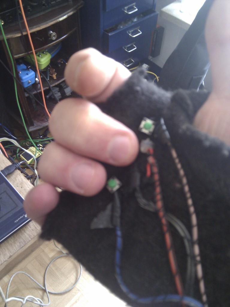
Push buttons and a force-sensitive resistor mounted on a glove
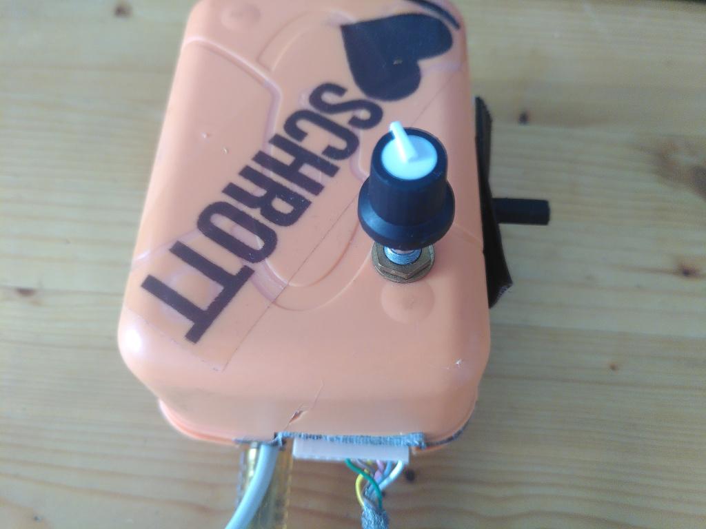
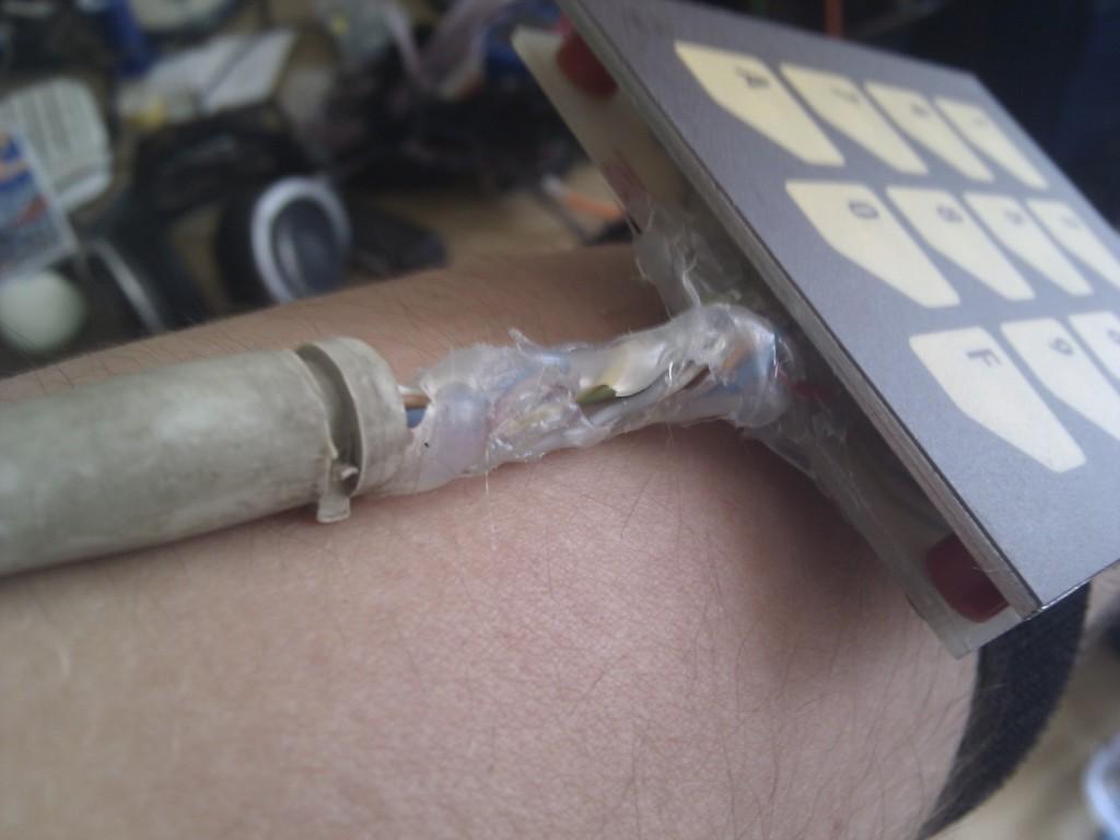
A keypad consisting of 12 push buttons with a resistor matrix.
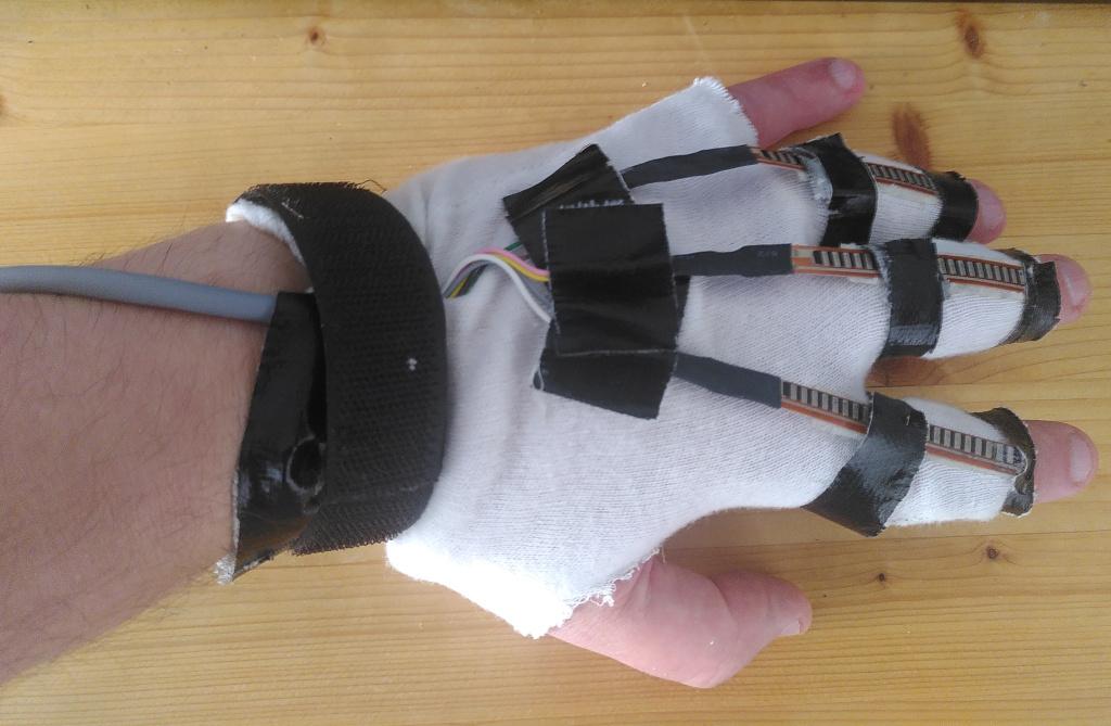
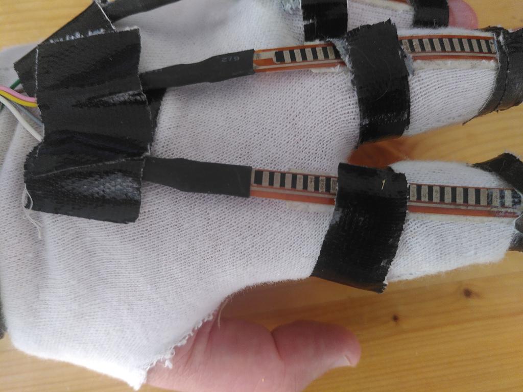
Various flex sensors mounted on a glove
Rotary encoder

Toggle Buttons


Toggle buttons are straight forward. This uses a pulldown resistor, marked as R1 in the schematics. Just use 20kΩ. The Arduino code sends a digital message, whenever the value changes. Debouncing is done with a time constant of 50ms.
#define DEBOUNCE_TIME 50

void readDigitalValue(int trigger, int &value, unsigned long &lastChange) {
    int arraySize = 1;
    if (millis() - lastChange < DEBOUNCE_TIME){
        return;
    }
    int tempValue = digitalRead(trigger);
    if (value != tempValue) {
        value = tempValue;
        byte data[arraySize];
        lastChange = millis();
        makeDigitalMessage(trigger, value, data);
        sendMessage(data, arraySize);
    }
}
Variable Resistors
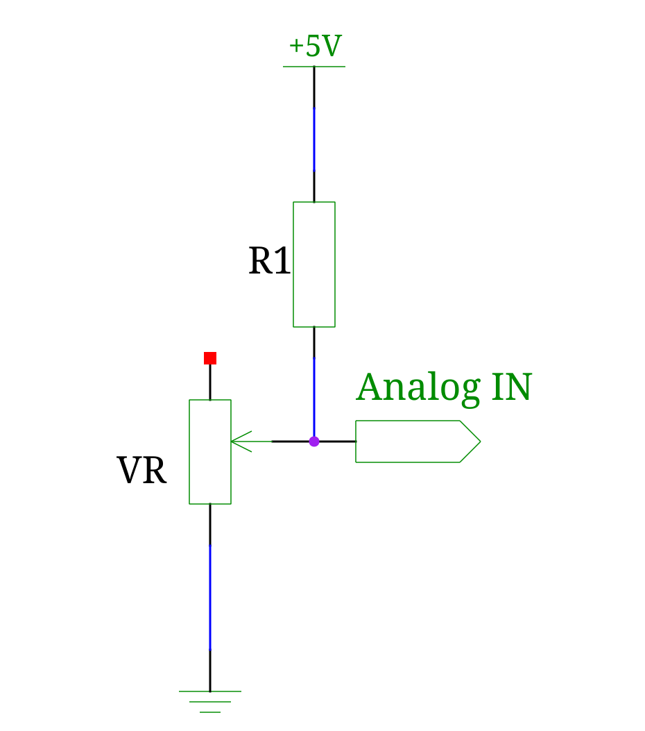
Variable resistors are a little bit more complicated. If these would be potentiometers, then the full range of values from 0-1023 would be available. But force resistive sensors and bend sensors only have two pins, and the value of the resistor is a range between a minimal and a maximum value, where minimal usually is not 0. So R1 must be added to get a voltage divider, and therefore a range of values. The range of values is from \({{R_{min}} \over {R1 + R_{min}}}\cdot 1024\, -\, 1\) to \({{R_{max}} \over {R1 + R_{max}}}\cdot 1024\, -\, 1\).
To get the best possible range of values, you must get closest to the geometric mean of the minimum and maximum value of the variable resistor, \(R1 = \sqrt{R_{max} \cdot R_{min}}\).
An example: If your variable resistor is between 20 kΩ and 110 kΩ, then you need a value as close as possible to \(\sqrt{20\cdot 110} k\Omega = 46.9 k\Omega \), i.e. 47 kΩ is the best match using standard resistor values. If this is not available, then use some other resistor closest to the calculated, if you only have other values around, as you can see in the table.
R1 (kΩ) |
Range |
Number of Values |
|---|---|---|
10 |
681 - 937 |
257 |
20 |
511 - 865 |
355 |
33 |
386 - 786 |
401 |
47 |
305 - 716 |
412 |
56 |
269 - 677 |
409 |
68 |
232 - 633 |
402 |
100 |
170 - 535 |
366 |
void readAnalogValue(int trigger, int &value) {
    int arraySize = 2;
    int tempValue = analogRead(trigger);
    if (value != tempValue) {
        value = tempValue;
        byte data[arraySize];
        makeAnalogMessage(trigger, value, data);
        sendMessage(data, arraySize);
    }
}
In Puredata, I use an abstraction to calibrate the minimum and maximum values, and scale them to floating point numbers from 0-1.
Rotary Encoder
A rotary encoder consists of 2 switches, that are alternating between on and off on rotation. They have overlapping stages of the on/off position, so that the code can distinguish between clockwise and counter-clockwise rotation. For details see this tutorial.
The encoder pins are directly connected to digital pins, no pullup or pulldown resistors needed, as the switches inside the encoder are connected to +5V and ground respectively on transitioning.
Rotating the encoder clockwise is increasing the value, counter-clockwise decreasing. The value starts at 0 and will wrap around at 1023, so that the data can be sent like a regular analog reading. I am using a value of 7 for the pin number to send out, because that pin number is not available on an Arduino Uno or compatible board.
void readRotary() {
    cwState = digitalRead(ROTARY_CW);
    if (cwState != prevCwState){
        if (cwState == HIGH) {
            if (digitalRead(ROTARY_CCW) == HIGH) {
                rotationSteps--;
            } else {
                rotationSteps++;
            }
        } else {
            if (digitalRead(ROTARY_CCW) == LOW) {
                rotationSteps--;
            } else {
                rotationSteps++;
            }
        }
        int arraySize = 2;
        byte data[arraySize];
        makeAnalogMessage(ROTARY_PORT_NUM, rotationSteps, data);
        sendMessage(data, arraySize);
    }
    prevCwState = cwState;
}
Keypad matrix
NB: This is not used anymore by myself, because it is easier to use a MIDI controller instead of going through all that hassle of calculating resistor values, debouncing, and only being able to press one key at a time. An alternative approach also is using the Keypad library from Arduino, although this uses 5 digital ins instead of just one analog in.
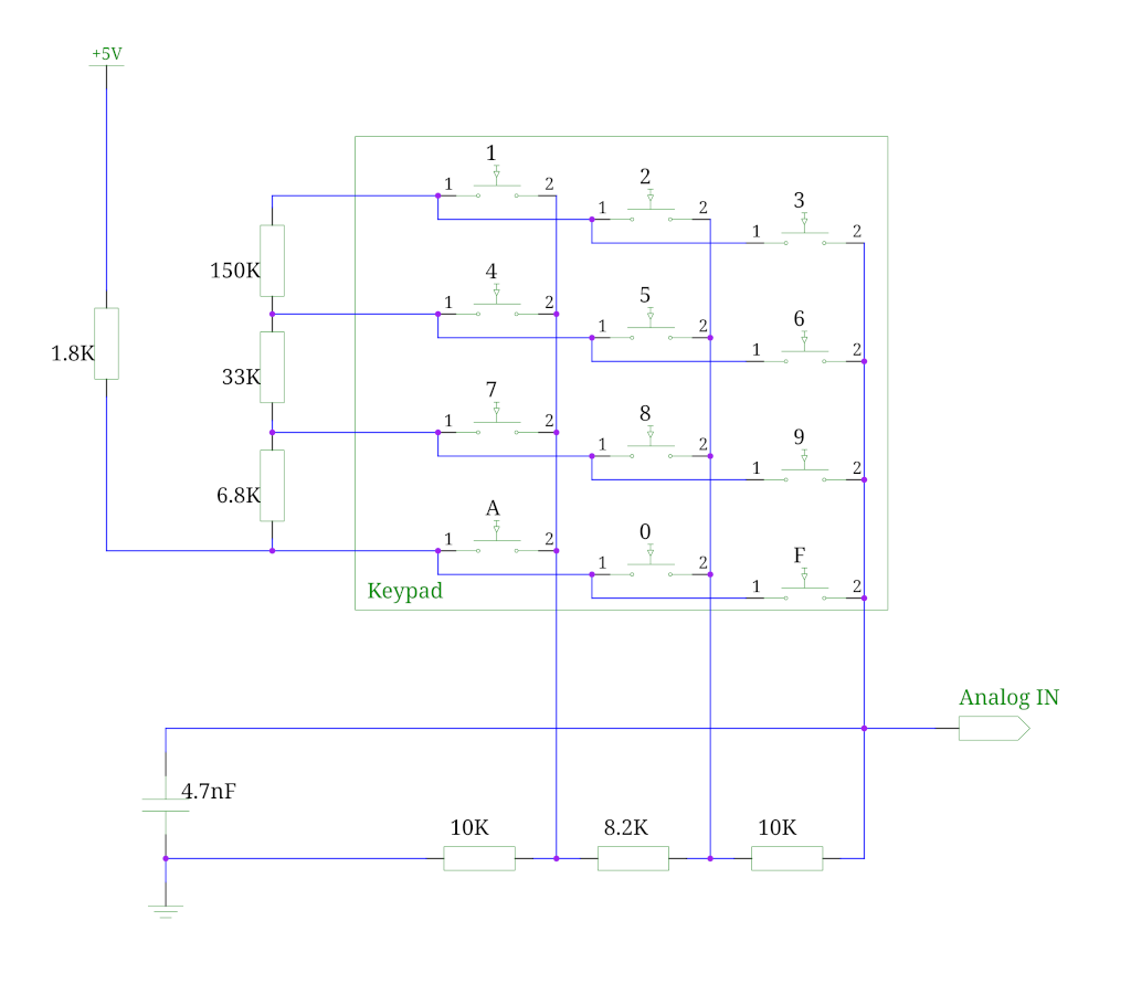
This reads an analog value, similar to Analog keypad library.
The resistor values are selected, such that different keys generate a different voltage division, and in turn a differrent analog value. That value is then sent to the computer.
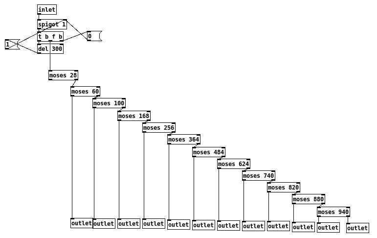
Debouncing is done in electronics with a 4.7nF capacitor, but also in Pd with a [spigot] and a delay of 300ms, because values are sometimes jittering.
Another idea to minimize sending key presses is to use a threshold for analog values to change before sending it, but this is also not failsafe.
#define ANALOG_ROUGHNESS 10

void readRoughValue(int trigger, int &value) {
    int arraySize = 2;
    int tempValue = analogRead(trigger);
    if (abs(value - tempValue) > ANALOG_ROUGHNESS) {
        value = tempValue;
        byte data[arraySize];
        makeAnalogMessage(trigger, value, data);
        sendMessage(data, arraySize);
    }
}
In Pd the key presses are detected by a chain of [moses] objects. The values of the boundaries were decided by measuring the values reported from the Arduino, because I have used the resistors I had lying around, which were 10% tolerance.
Message Passing between Arduino And Pd
I wanted to minimize the data sent from Arduino over USB to the host computer. I came up with the following encoding, that uses 1 byte for a digital value and 2 bytes for analog values.
- Digital message
-
100ppppv - Analog message
-
11pppvvv0vvvvvvv
p denotes bits used for encoding the pin number, v bits used for values.
As the Arduino Duemilanove or the Arduino Uno - the ones that I use - have 14 digital pins, 4 bits (0-15) are necessary to encode the pin number, 6 analog ins can be encoded in 3 bits (0-7), giving the possibility to add two additional analog values, e.g. the rotary encoder. Digital pins only read 0 or 1, so only one bit is needed for encoding the value, analog pins read values 0-1023, which corresponds to 10 bits.
void makeDigitalMessage (int port, int value, byte *data) {
    data[0] = 0x80 | (port << 1) | value;
}

void makeAnalogMessage (int port, int value, byte *data) {
    data[0] = 0xc0 | (port<<3) | ((value >> 7) & 0xff);
    data[1] = 0x00 | (value & 0x7F);
}
If a byte starts with a value of 11, then this byte and the following one starting with 0 together are an analog message. If a byte starts with 100, then the message is a digital message.
On Pd's side, messages are parsed and then output in the same way as [pduino] does it: (a|d) [pin number] [value]. That design allows it to be used as a drop-in replacement.
I first tried to parse messages in a Pd abstraction with bit shifting in [expr], but that was too CPU intensitive, so I have created an external in C. That external does the bit shifting and then outputs messages as lists.
void new_byte(t_arduino_message_parser *x, t_floatarg new_value) {
    int prev_byte = x->first_byte;
    int port = 0;
    char port_type = 0;
    int value = 0;
    int new_value_int = new_value;

    if (prev_byte > 0 && (new_value_int & 0x80) == 0) { /* analog, 2nd byte */
        port_type = 'a';
        port = (prev_byte >> 3)  & 7;
        value = ((prev_byte & 7) << 7) + (new_value_int & 0x7f);
        x->first_byte = 0;
    } else if ((new_value_int & 0xc0) == 0x80) { /* digital */
        port_type = 'd';
        port = (new_value_int & 0x7f) >> 1;
        value = new_value_int & 1;
    } else if ((new_value_int & 0xc0) == 0xc0) { /*analog, 1st byte */
        x->first_byte = new_value_int;
    }
    if (port_type == 0) {
        return;
    }
    t_atom out[3];
    char out_data[2];
    sprintf(out_data, "%c", port_type);
    SETSYMBOL(&out[0], gensym(out_data));
    SETFLOAT(&out[1], port);
    SETFLOAT(&out[2], value);
    outlet_list(x->x_obj.ob_outlet, &s_list, 3, &out[0]);
}
Pd Patch
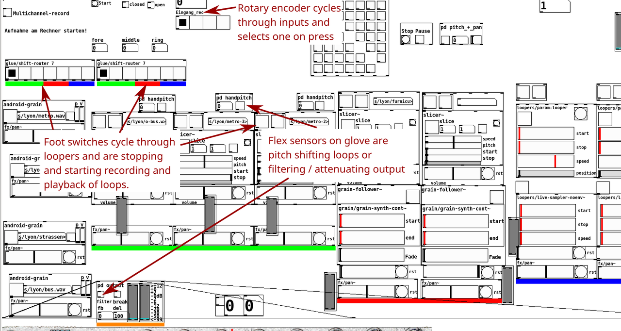
I am using the setup mostly for live performances, and the demo patch included in the source code is the actual patch that I use. It also makes heavy use of my abstractions.